
Pogo Pin Types Explained: A Complete Guide to Spring Pin Classification from Structure to Applications
Pogo pins (spring-loaded pins) are precision spring-loaded probe connectors widely used in smartphones, wearable devices, automotive electronics, medical equipment, and aerospace applications. Their core function is to transmit current and signals within electronic devices. Thanks to their compact size, light weight, and reliable connectivity, they have become indispensable components in modern electronic design.
However, with the vast array of pogo pin products on the market, selecting the right type for specific requirements is a common challenge for engineers and procurement professionals. This article systematically reviews the common classification methods for pogo pins to help you quickly establish a selection framework. For foundational concepts, you may also refer to our Basic Knowledge of Pogo Pins guide.
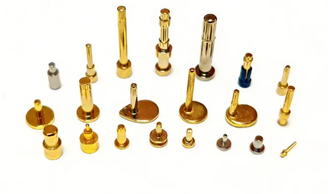
1. Classification by Mounting Method
This is the most fundamental classification dimension, primarily determining how the pogo pin connects and solders to the PCB board.
1.1 Flat Bottom Type (Vertical / SMT Type)
Structural features: The bottom of the barrel is a flat surface, and the bottom outer diameter is slightly larger than the barrel outer diameter, facilitating vertical surface mounting on the PCB.
Applications: Mainly used for board-to-board connections, or protruding from the device housing as external contact points. It is also suitable for waterproof structural designs. This mounting method occupies the least PCB space and is ideal for high-density layouts.
1.2 Through-Hole Type (DIP / Tail Pin Type)
Structural features: A tail pin extends from the bottom of the barrel for insertion into through-holes on the PCB for soldering. Some designs allow the tail pin to be bent at specific angles to accommodate different mounting orientations.
Applications: Scenarios requiring stronger mechanical bonding, especially in high-vibration environments where through-hole soldering offers superior reliability compared to SMT. Additionally, through-hole types support multi-pin array integration with plastic housings.
1.3 Bent Type
Structural features: A variant of the through-hole type, where the tail pin is bent so that the pogo pin can be mounted at an angle relative to the PCB.
Applications: When internal device space is limited and vertical mounting is not feasible, the bent type provides a flexible alternative.
2. Classification by Plunger Tip Structure
The shape of the plunger tip directly affects contact reliability and service life. Common tip shapes include pointed, round (ball), flat, crown (claw), serrated, and tulip tips. Different tip designs correspond to different application requirements:
- Pointed / Crown tips: Can penetrate solder paste or oxide layers to reach clean metal surfaces, especially suitable for PCB test fixtures.
- Round / Ball tips: Maintain signal continuity during relative movement between contacts, suitable for dynamic connections or sliding scenarios.
- Flat tips: Offer a large contact area, suitable for high-current transmission.
3. Classification by Functional Characteristics
This is the most critical dimension in product selection, directly determining whether the pogo pin meets the product’s electrical and environmental requirements.
3.1 High-Current Type
Typical specifications: Standard pogo pins carry 0.5–3A, while high-current types can reach 5A–60A. Standard SMT types typically max out at 5A, while custom high-current designs can extend to 40A.
Applications: Charging docks, battery connections, power modules, and other high-power applications.
3.2 High-Frequency Type
Performance metrics: Supports data transmission rates up to 10 Gbps.
Applications: High-speed signal transmission, such as antenna connections and high-frequency testing. For more details, see our guide on Key Factors for Stable Antenna Pogo Pin Connections.
3.3 Waterproof Type
Structural features: Built-in sealing structure prevents water and moisture intrusion.
Applications: Outdoor equipment, smartwatches, sports earphones, and other products that may come into contact with sweat or rain.
3.4 Magnetic Type
Structural features: Uses magnetic force to establish and maintain secure polarized connections.
Applications: Applications requiring quick plug-and-play with directional self-alignment, such as magnetic charging docks for smartwatches. Learn more from our AI Glasses Magnetic Charging Solution Selection Guide.
3.5 Low-Force Type
Structural features: Designed with reduced spring tension to apply minimal pressure at the contact point.
Applications: Connecting pressure-sensitive precision components, avoiding damage to mating surfaces from excessive normal force.
3.6 Threaded Type
Structural features: The plunger or barrel features threads for secure fastening to boards or equipment.
Applications: Installation scenarios requiring additional mechanical fixation to enhance connection stability.
3.7 Solder Cup Type
Structural features: The pin tail features a small solder cup for direct cable soldering.
Applications: Scenarios where pogo pins connect to cables rather than being soldered directly to the PCB.
4. Classification by Special Structures
Non-conventional structural designs designed to meet specific application scenarios.
4.1 Double-Ended Type
Structural features: Both ends are retractable spring-loaded contacts.
Applications: Establishing connections between two PCB boards, with each end contacting pads on respective boards without the need for additional intermediate connectors.
4.2 Floating Type
Structural features: Similar in appearance to the double-ended type, but one end is a standard spring contact structure while the other end is a curved surface (non-spring structure). This design allows a certain floating margin and prevents over-compression. Some floating connectors use press-fit installation without soldering, adapting to different gaps through vertical floating.
Applications: Scenarios with tight installation tolerance requirements, or designs that need to absorb positional deviations between PCB boards.
4.3 L-Type (Right-Angle Type)
Structural features: Mounted horizontally at a 90° angle to the PCB.
Applications: Used when internal device height space is limited and the connector needs to be arranged horizontally.
5. Key Electrical Parameters for Pogo Pin Selection
After determining the pogo pin type, the following core electrical parameters must be considered, as they directly affect product reliability:
| Parameter | Typical Range | Selection Advice |
|---|---|---|
| Rated Current | Standard 1–5A, high-current up to 40A | Insufficient current causes heating and contact degradation |
| Contact Resistance | 20–50 mΩ (standard), gold plating below 30 mΩ | Lower is better; excessive resistance causes signal loss and heating |
| Spring Force | 50–200 gf (standard), customizable | Too little causes momentary disconnection under vibration; too much accelerates plating wear |
| Mating Cycles | 10,000–1,000,000 cycles | Industrial standard is typically 100,000+ cycles; must exceed product service life requirements |
| Working Stroke | Varies by product specification | Design using working stroke rather than maximum stroke to avoid spring fatigue |
Summary and Selection Recommendations
When selecting pogo pins, we recommend making decisions in the following order:
- First, define current and voltage requirements — determine whether a high-current or high-frequency type is needed;
- Then estimate mating cycle count — distinguish between consumer-grade (low lifespan) and industrial/test-grade (high lifespan);
- Next, consider PCB space and mounting method — decide between SMT, through-hole DIP, or right-angle/L-type mounting;
- Factor in environmental conditions — whether special functions such as waterproof, magnetic, or low-force are required;
- Finally, select plating material — gold plating offers the best performance but at higher cost, while nickel plating is an economical baseline option.
If you encounter connection reliability issues after deployment, our article on Troubleshooting Pogo Pin Contact Issues provides in-depth analysis of root causes and solutions.
By mastering the pogo pin classification knowledge above, you will be able to make more precise component selections early in the product design process, achieving the optimal balance among reliability, performance, and cost. As a professional pogo pin manufacturer based in Shenzhen, WOYO Technology offers comprehensive customization services to meet your specific application requirements.